Electric charge
What is electric charge?
In a simplified atomic model, electrons orbit about a central nucleus containing protons and neutrons.
Charge is a fundamental property of electrons and protons.
We use the concept of charge to explain how particles like protons and electrons exert forces on each other.
How do atoms become charged?
As long as the number of electrons equals the number of protons, an atom is neutral (it has no net charge).
If an electron is removed from an atom, the atom has a net (+) charge and is then called a cation.
If an electron is added to an atom, the atom has a net (-) charge and is called an anion.
What is the charge of an electron?
Most people would say -1. But what is it measured in?
However, the Coulomb (C) is the unit for electric charge.
The charge on one electron is approximately -1.602 x 10⁻¹⁹ C. The Information Sheet gives the charge on an electron the symbol e.
What happens when electrons move?
The process of moving electrons can happen on a large scale as well as an atomic scale, leaving macroscopic objects charged.
Electrons can be added or removed from a body (a material object). The object then has an excess or a deficit of electrons and we say that the object has been charged. The material has an electrostatic charge.
- If an object has an excess of electrons (more electrons than protons) then it has a negative charge.
- If an object has a deficiency of electrons then it has a positivecharge.
- If a body is neutral then the number of electrons equals the number of neutrons.
How to calculate the charge on an object?
How many extra electrons are there on a body with a charge of -1 Coulomb?
The charge, Q, on a body equals the number of electrons lost or gained multiplied by the charge on an electron.
Where e = the charge on an electron.
While this formula isn’t on the information sheet there is no need to memorise. It’s intuitive: electrons are charge carriers. If an object is charged it must have gained or lost electron.
How do charged objects behave?
Like charges attract.
Unlike (or opposite) charges repel.
How do neutral bodies respond to charged bodies? (extension)
Neutrally charged objects can also experience a force due to other charges.
A neutral object will experience a force when close to a charged object, because of how the molecules change shape or alignment when a charged object is brought close.
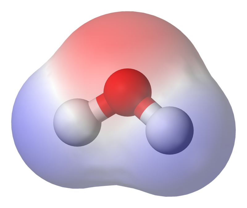
In some molecules, the molecules naturally have polarity – basically more electrons on one side than the other (like water molecules). In others, a charged object can induce polarity in the particles.
Why is there a net force between charged and neutral bodies? (extension)
You would think that because the positive side of the molecules experiences an attractive or repulsive force and the negative side experiences the same force in the opposite direction, there would be no net force between the molecules and the balloon. This would be true if the electric field was uniform, but it’s not. The field is stronger closer to the charged object.
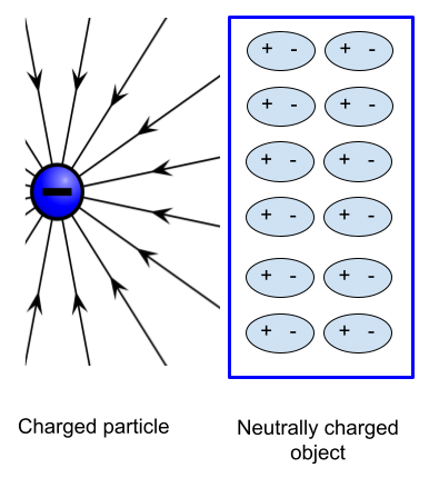
In the diagram, because the positive sides of the molecules in the neutral object are closer to the negative charge, the attractive force they experience is stronger than the repulsive force experienced by the negative side. The result is a net force.
For this reason, many neutral objects are attracted to charged objects.
What is the law of conservation of charge?
Charge is a conserved quantity; in any process the total amount of charge remains constant.
The law of conservation of charge states that charge can be neither created nor destroyed.
Obviously charge can be transferred from one object to another.
Thus we can build up a negative charge on a balloon, but only at the expense of leaving behind an equal positive charge on a wool sweater.
Because of this, positive and negative charges are always produced in equal amounts at the same time.
How is charge conserved during beta decay?
The law of conservation of charge helpt to explain why a beta particle is created at the same time as a proton during beta minus decay.
What are conductors and insulators?
A conductor is a material that contains charge carriers; that is, charged particles which are free to move through the material. For example:
- salt solutions — the charge carriers are positive and negative ions that are free to move through the solution
- metals — the charge carriers are electrons
An insulator is a material that contains no or very few charge carriers. Common insulating materials are dry air, glass, plastics, rubber and ceramics. If an insulator is given an electrostatic charge at a particular area on the insulator, the charge will remain at that area.
Roughly speaking,metals are good conductors, nonmetals are good insulators, and metalloids are good semiconductors.
The movement of charge in conductors
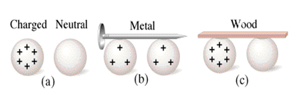
A charged metal sphere and a neutral metal sphere.
When connected by a good conductor the charge will flow between the charged and neutral sphere until it is evenly distributed.
When connected by an insulator almost no charge is conducted
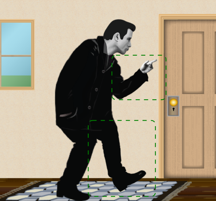
How do objects become electrically charged?
One way of transferring electrons is by rubbing one material against another. Objects can also become charged by taking away pieces of molecules, leaving other pieces behind. If these pieces have a net charge, then the object will become charged. Again, this usually happens by rubbing.
This is the process that occurs when you slide down a plastic slide and your hair stands up, or when you walk across a carpet and get a small shock when you touch a door handle.
Why is it called the electrostatic force?
The following provides background information:
We call the force that charged objects, including charged particles, exert on each other the electrostatic force.
The ‘static’ in electrostatic means that this force acts when the charged objects are not moving. It also acts when the objects are moving, but when charges move they also exert a magnetic force (coming up).
Electrostatics deals with the simple case when we do not need to consider the magnetic force.
Electric current
What is electric current?
electric current is the rate of flow of charge past a given point
In other words, current, I, is the amount of charge flowing per second
The SI unit of current is the ampere (A), abbreviated to amp. It’s actually equivalent to a coulomb of charge per second (Cs-1)
What is the direction of current?
In a DC circuit, electrons flow from the negatively charged terminal of the cell/battery/power supply to the positively charged terminal.
Electric potential difference
What is electric potential difference?
The Electric Potential Difference, ΔV, between two points is the change in potential energy, ΔE, per unit charge, q, moving from one point to the other.
Electric Potential Difference is also called Voltage.
Electric potential difference can be given the symbol ΔV, but in practice, we leave out the delta.
The units of electric potential difference are Volts (V) or Joules per Coulomb (J/C).
Because work is equal to change in energy:
Current flow in electric circuits
What makes current flow?
There are three conditions required for an electric current to flow:
- a path for the current to flow along
The path in an electric circuit is made of the components of the circuit (e.g. wires, resistors). - charge carriers (charged particles) that are free to move
The charge carriers in an electric circuit are electrons. - a force applied to make them start moving
When a circuit is completed, the potential difference across the terminals of the cell/battery/power supply creates an electric field in the wires/components of the circuit. The electrons in the circuit experience a force and move as an electric current as a result of the electric field.
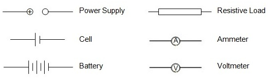
What circuit symbols should you know?
Energy in electric circuits
What is the Voltage of a component in a circuit?
In a circuit, we often refer to voltage of a component, which is simply another way of saying the electric potential difference across the component.
The voltage of a component is a measure of the electric potential energy gained or lost by the electrons (charges) as they move from one side of the component to another.
Voltage, V, (potential difference) is measured in volts and is given the symbol V. Sorry about that.
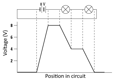
How does voltage change in a circuit?
Electric charges gain electrical energy as they pass through the power supply in a circuit.
They then lose the electrical energy they have gained as they move through the circuit. This energy is transformed into other forms of energy e.g. light energy if a light bulb is attached to the circuit.
Electrons lose energy as they pass through a component such as a light globe. This results in a voltage drop across the component. The voltage drop depends on the resistance of the component.
Why must the voltage of the power supply equal the sum of the voltage of all the components?
What are resistors?
Technically, all conductors resist current to some degree.
However, connecting wires for electric circuits are made so that there is negligible conversion of electric potential energy into heat energy when a current passes through them.
So these components are referred to simply as conductors.
In other components (the load), the conversion of electric potential energy into heat energy cannot be neglected.
These components are referred to as resistors.
When an electric current flows through a resistor it loses electric potential energy, and heat energy is generated.
How does potential difference change across resistors?
In a resistor, electric potential energy is converted into other forms of energy. The electric potential energy is said to be dissipated.
The potential difference across a resistor is the number of joules of electric potential energy dissipated by each coulomb of charge that passes through the resistor.
Potential difference across a resistor is commonly referred to as the voltage across the resistor.
If energy, W, is dissipated when a charge, q, moves through the resistor, then the voltage, V, across the resistor is given by the formula:
For example, if there is a potential difference of 1000 V between the ends of the element in an electric heater, then for each coulomb that passes through the element, 1000 J of electric potential energy is converted into heat energy.
Current and voltage in series and parallel circuits
Investigating current
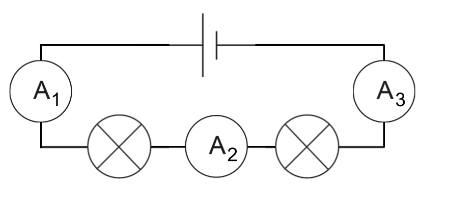
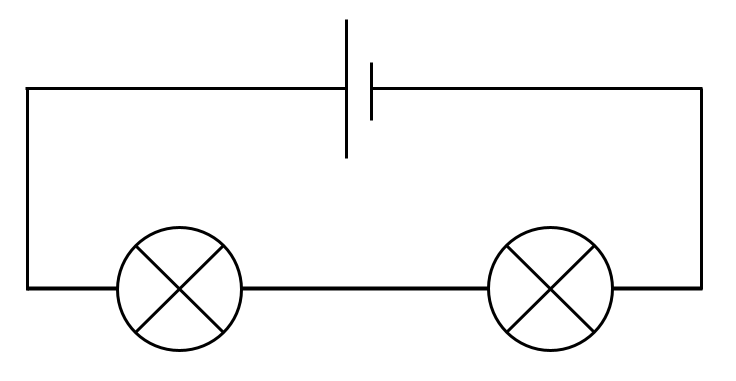
in circuits with resistors connected in series
The current is the same in all parts of the circuit
I1 = I2 = I3
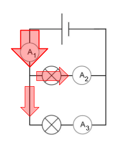
in circuits with resistors connected in parallel
The current flowing through A1 is equal to the sum of the current flowing through the other parts of the circuit
I1 = I2 + I3
Investigating voltage
in circuits with resistors connected in series
The potential difference across the power supply is equal to the sum of the potential difference in all the resistors
V1 = V2 + V3
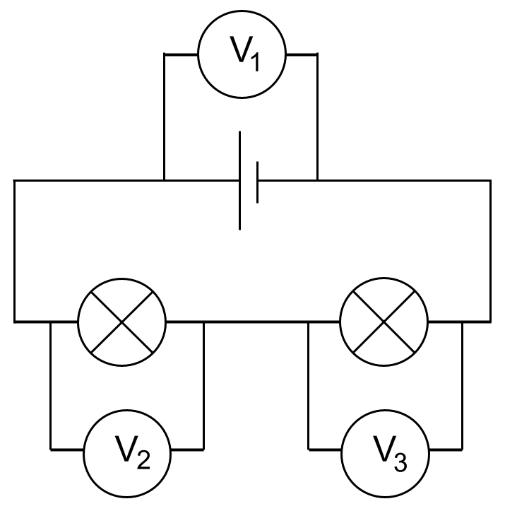
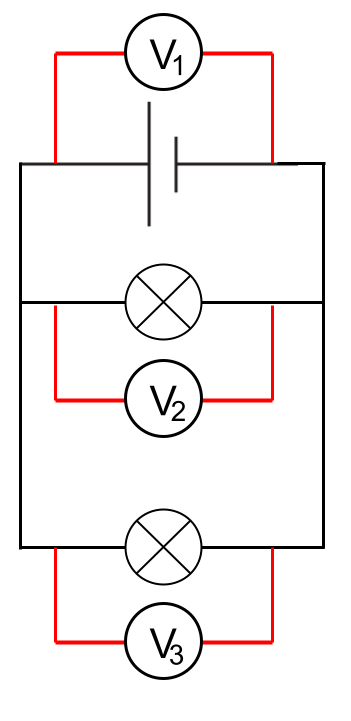
in circuits with resistors connected in parallel
The potential difference across each resistor is equal to the potential difference across the power supply
V1 = V2 = V3
How is energy conserved in a circuit?
The potential energy of the charged particles changes as they move around a circuit, like the one shown. As the particle moves through the resistor, its potential energy decreases.
By applying the law of conservation of energy, we can say that the energy gained by a charge as it moves through a power source (e.g. a cell) must equal the energy lost by the charge when it passes through resistors. In other words, whatever decreases in potential energy it had from passing through the resistors must be equal to the potential energy gained by passing through the battery.
Why is current conserved in a circuit?
Consider the circuit below. If the three currents I1, I2 and I are measured it is found that I = I1 + I2
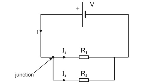
This is a consequence of the law of conservation of charge.
Remember that current readings correspond to numbers of electrons (charged particles) passing per second.
An analogy for understanding Current in circuits with resistors in parallel
Consider vehicles at a road junction.
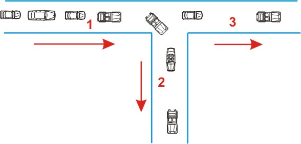
The number of vehicles passing point 1, per minute, must be equal to the number of vehicles passing point 2 per minute plus the number of vehicles passing point 3 per minute.
You could say that the number of vehicles is conserved.
The Current voltage relationship
What is the relationship between V, I and R?
When a current, I, passes through a resistor, electric potential energy is dissipated, so there will be a potential drop, V, across the resistor. The resistance, R, of a resistor is defined as the potential difference V across its ends divided by the current I passing through it:
- The SI unit of resistance is the ohm (Ω).
- If a current of 1 A is passing through a conductor of resistance 1 Ω, the potential difference between the ends of the conductor will be 1 V.
- Good conductors, like connecting wires, have zero or negligible resistance.
Ohm’s Law
What is Ohm’s Law?
The relationship between voltage and current is: V = IR.
This is NOT Ohm’s Law.
If a resistor obeys Ohm’s law, then its resistance is constant, independent of the current flowing through it or the potential difference across it.
Ohm’s Law applies only to resistors with constant resistance; that is, to resistors whose resistance is the same no matter what current is passing through them.
For such resistors,
Resistors that obey Ohm’s Law are called ohmic resistors.
Many important resistors do not obey Ohm’s law, especially if their temperature changes, e.g.:
- incandescent bulbs (because their temperature changes as current changes)
- diodes including LEDs
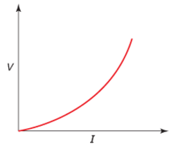
Graphs of Voltage vs Current (V vs I)
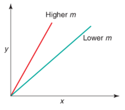
Recall that if y is directly proportional to x, (y ∝ x), then a graph of y against x will be a straight line described by the equation y = mx.
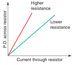
Similarly, if V ∝ I, then a graph of V against I will be a straight line described by the equation V = RI, where R is equivalent to the gradient of the graph
For a non-ohmic resistor, the graph of V against I is not a straight line becuase the resistance isn’t constant.
Which way to draw the graph?
In physics, we often select our axes for convenience.
Because the relationship between voltage and current is V = RI, graphs of voltage versus current (where voltage is a function of current, or voltage is the ‘dependent’ variable) are common. The value of the gradient of the line on these graphs is the resistance.
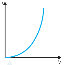
In experiments, we often change the voltage across a resistor and measure the current through it. For this reason, graphs of current versus voltage (where current is a function of voltage, or current is the ‘dependent’ variable) are a little more intuitive.
The value of the gradient of the line on these graphs,
Many important circuit components do not obey Ohm’s Law, including incandescent (filament) light bulbs, and light emitting diodes (LEDs).
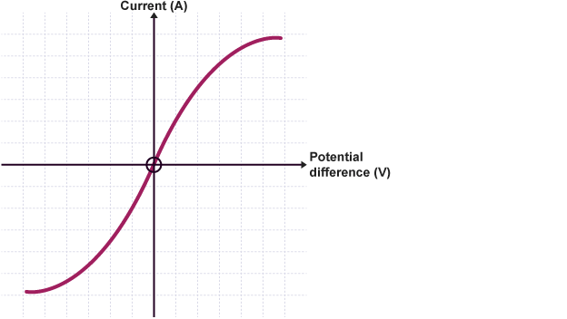
Graph of current versus voltage for an incandescent light bulb.
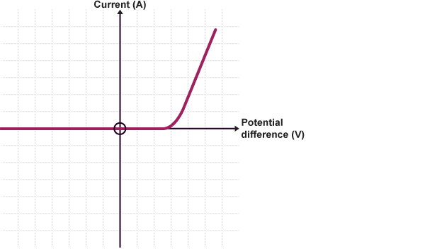
Graph of current versus voltage for a LED.
Power
What is Power?
Power, P, is the rate at which energy is transformed from one form to another
The units of power are Watts (W) or Joules per second (J/s).
Technically, this equation gives the average power, Pav, but this is a distinction that you don’t usually have to worry about because the power is usually constant in question that you will be asked to solve.
Since Work is simply energy being transferred or transformed, we can write the Power equation as:
What is the power dissipated by a resistor?
You are not required to derive any equations in this course, but the formula for power in an electric circuit is very simple to derive:
We can use R = V/I to rewrite the formula for power in equivalent ways:
Kilowatt hours
Why use kilowatt-hours instead of Joules?
The joule is a very small unit of energy. A typical 1000 W heater uses 7.2 ✕ 106 Joules of energy in 2 hours.
That’s just one device, for a small amount of time. Imagine how much energy is used for a three month period by an entire household.
We need an alternative and more convenient unit of energy (e.g. for household electricity accounts).
A kilowatt-hour (kW-h) is defined as the amount of energy used by a 1 kW device in 1 hour. To calculate the power used/transformed by an electrical device:
energy (kWh) = power (kW) × time (h)
How to convert kilowatt hours to Joules?
Normally we want energy in joules (J) and time in seconds (s). How much energy is that in Joules?
The kW is equal to 1000 W (1000 J/s). The hour is 3,600 seconds, so:
1 kWh = 1,000 J/s × 3,600 s
1 kWh = 3,600,000 J = 3.6 × 10⁶ J
1 kWh = 3.6 MJ (megajoules) = 3.6 × 10⁶ J
Energy efficiency
What does efficiency mean?
Some energy transformations are more efficient than others.
Efficiency is a measure of the amount of useful energy we get out of something that transforms energy compared to the amount of energy we put in.
Whenever energy is transformed, the conversion is never 100% efficient.
For example, the amount of light energy made by a light bulb is always less than the amount of electrical energy put in!
Doesn’t this break the Law of Conservation of Energy? Where did the energy go?
How to calculate efficiency?
Remember, energy is measured in Joules but efficiency is given as a percentage.
What about efficiency and power?
Because energy transformations are continuous (e.g. in a power station), we usually consider the energy transformations in terms of Power.
efficiency, e, can be defined as:
(remember, efficiency is usually expressed as a percentage).
If a light is 80 % efficient, how much power is needed to produce 10 Watts of power as light?
Total resistance in Series and parallel circuits
What is the difference between series and parallel?
How do we label circuit components?
When we deal with circuits with more than one resistor, it is convenient to label the resistors R1, R2, and so on.
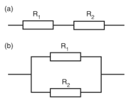
- The resistances of the resistors are labelled R1, R2 and so on. (Note the use of italic to denote a variable, i.e. resistance.)
- Currents through the resistors are labeled I1, I2,
- Voltages across the resistors are labelled V1, V2, and so on.
It is sometimes easier to solve problems by total resistance of a circuit or part of a circuit.
The total resistance of resistors connected in Series
If n resistors, with resistances R1, R2 … Rn, are connected in series to a power supply, the total resistance is:
What is the total resistance of resistors in parallel?
When resistors are connected in parallel, the total resistance is always less than the resistance of any of the parallel resistors.
For two resistors connected in parallel (the most you’ll need to deal with in this course):
You have to take care when using the formula above to ensure that you find Rtotal. You will probably prefer the following formula:
- Adding resistances in parallel decreases the total resistance and increases the total current!
- This has serious implications for household electricity.
More complex circuits
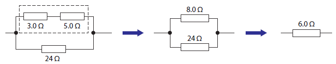
A typical circuit will contain both parallel and series connections.
In the diagram, the two top resistors are in series. They are equivalent to a single resistor of 8.0 Ω. This resistor and the 24 Ω resistor are in parallel, so together they are equivalent to a single resistor of:
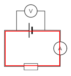
Ammeters and Voltmeters
How are ammeters and voltmeters connected?
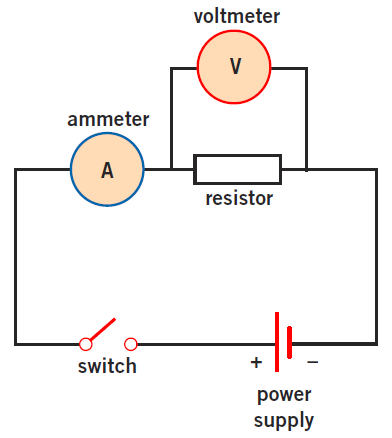
To measure current flowing through a component, ammeters are connected in series with the component.
To measure potential difference (voltage) across a component, a voltmeter is connected in parallel with the component.
Why are ammeters and voltmeters connected differently?
An ammeter has very low resistance. When it is connected it does not significantly change the current in the circuit.
A voltmeter has a very high resistance. When it is connected it does not significantly change the current in the circuit.
We usually assume that ammeters have zero resistance and voltmeters infinite (∞) resistance.
Ideal voltmeters
Ideal voltmeters have infinite resistance
Voltmeters are connected in parallel and read the potential difference across only the component it is in parallel with.
The green current represents the amount of current the battery needs to supply to the voltmeter in order to make it register.
The red current is the amount of current the battery supplies to the original circuit.
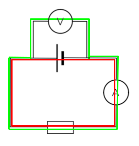
In order to NOT ALTER the original properties of the circuit, ideal voltmeters have extremely high resistance (∞ Ω) to minimize the green current.
Not all Voltmeters are ideal voltmeters. That is, some current passes through them.
Ideal ammeters
The ammeter is supposed to read the current of the original circuit (without the ammeter).
In order to NOT ALTER the original properties of the circuit, ideal ammeters have extremely low resistance (0 Ω) to minimize the effect on the red current.